You are now the proud owner of an original Kiwi Feather Prop™ which has been carefully designed and engineered to deliver many years of carefree service on your vessel. There are some very simple recommendations you should be aware of to ensure your Kiwi Feather Prop™ will continue to deliver trouble free performance in the years ahead.
Before fitting your new Kiwi Feather Prop™ first check that the shaft is free to rotate and can
be spun easily by hand to ensure correct feathering. Remove the nut from the Boss by releasing the locking screws. Wipe all
mating surfaces clean and lightly smear with a marine grease including both keyways.
Check that the taper length will allow the nut to pull the propeller tight on to the shaft.
In all cases the boss should protrude ~1/4 inch longer than the small end of the taper, which is the SAE standard, to ensure the nut pulls
up on the boss correctly and doesn't bind on the thread.
To ensure the key is fitted correctly, mount the unit without the key, to ensure the taper is tight, and then again with the key to ensure
it is not binding on the keyway which can then be ground down if required. [Larger 1.125" and 1.250" units mount 0.250"
and 0.625" respectively down from the start of the taper ] Check the fitting of the nut prior to mounting the
propeller and remove any burrs or impediments to the smooth operation of the nut. Smear the thread with a marine grease.
A new key will be supplied for all 1 1/4 inch shafts with one face ground down by 0.025" which allows for a common boss size.
Ensure the ground face is mounted outwards. Always replace any key that is old or shows any signs of corrosion. Keys are usually only
a brass and will corrode rapidly. The shearing of a corroded key will result in the automatic loss of your new propeller.
Saildrives require a similar approach. Ensure that both internal and external splines are scrupulously clean to avoid binding and that
the ~10 mm thick collar with shield which acts as a seal guard is on the shaft. Check the Delrin nose cone is not binding on the zinc.
Some units such as Lombardini come with washers which must be mounted. All Saildrives require that the distance from the end of the
spline to the face taking the thrust is exactly 3.000". All Saildrive propellers then have bosses which are ~ 3.125" long to
ensure they pull up tight on the thrust face before the M16 (M20 for SD40) nut starts to bind at the end of the thread.
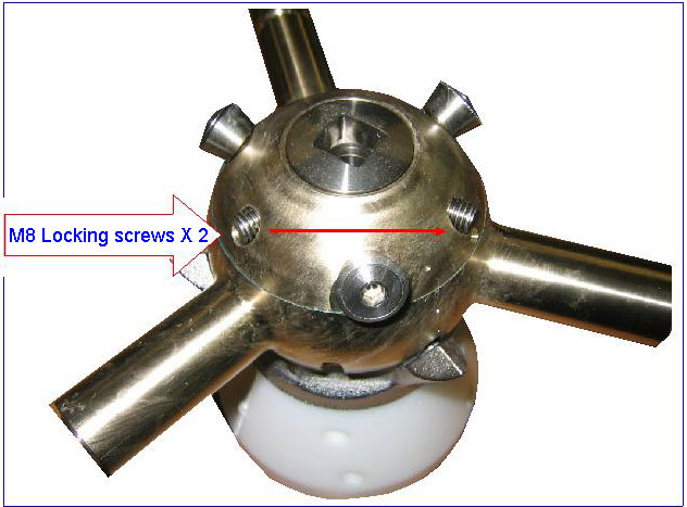
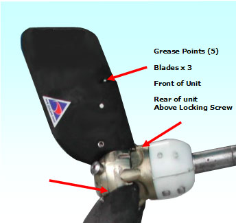
The photograph below shows a boss without the blades attached and clearly identifies the nut with itÆs Įö square drive and the two locking screws that must first be backed off to allow for removal of the nut from the unit.
These same locking screws must then be coated in LoctiteÖ before being wound back into the boss and tightened down to ensure the nut retaining the propeller is correctly locked in.
NB: A FAILURE TO TIGHTEN THESE TWO LOCKING SCREWS AND SECURE WITH LOCTITEÖ WILL INVARIBLY LEAD TO THE LOSS OF THE ENTIRE PROPELLER UNIT.
Do not over tighten the nut which attaches to any standard 1/2 inch socket driver. This is particularly important on tapered shafts when you need to remove the propeller and when using the Delrin nut option. Just nip it up using no more than 10 foot lbs of torque. This is equivalent to the weight of a one gallon or five litre can of water suspended on your socket driver one foot or 300 mm from the nut.
Apply a drop of Loctite ™ to the 2 x 8mm grub or set screws located on the hub of your KiwiProp which are used to then lock the nut onto the shaft using the appropriate Allen key
Again .. do not over tighten, particularly when using the Delrin nut
NB: Saildrive nuts and their locking screw should be checked and re-tightened at each haulout as Splines by their nature may fret slightly in use and could loosen the locking screws.
To ensure the propeller feathers correctly, first throttle down to an idle, and then place the gearbox in neutral before stopping the engine. The shaft will then slow down as the blades align themselves with the water flow and quickly come to a stop. The shaft will then remain stationary without further attention.
Keep the gearbox in neutral whenever you are sailing.
You are now ready to enjoy the ongoing benefits from your Kiwi Feather Prop™
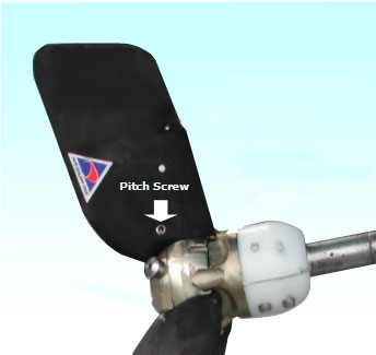
The Kiwi Feather Prop™ will have been set at the recommended pitch for your installation based on the engine model number, the reduction gear fitted and the particular characteristics you supplied of your vessel. You may however wish to take advantage of the simple pitch adjustment feature to accommodate the many variations between individual vessels and operating preferences and obtain the optimal motoring performance for your particular requirements. One turn of the 8 mm pitch screw in a clockwise direction to each blade in turn will equate to 3 degrees of pitch [not inches of pitch] and substantially increase the power required from the engine and drive train. This will translate to lower engine revs. We would recommend adjustments be made in no more than exact half turn increments to each blade, which has the effect of varying engine revs by some 300 ~ 400 rpm. Each installation is unique and only experience can deliver the
apropriate settings and optimal cruising revs for your vessel. A pitch setting of 20 degrees equates to a normal pitch of ~ 11 to 12 inches.
[ The required Allen key is 5/32" or 4 mm ]
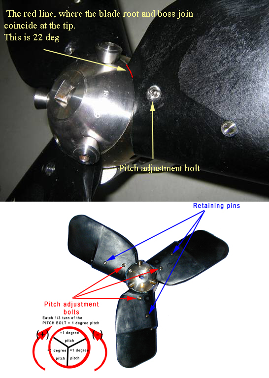
To maintain an equal pitch on each blade, were this to be lost, or required if a blade was replaced, use the following procedure. When the aft face of the blade root is aligned with the joint line between the mushroom end holding the reversing rollers which rotates, and the boss which carries the blades, then the pitch is equates to 20 degrees on older blades.
For units with a serial # > 446 and new blade dies this equates to an 18 deg null.
Simply adding or subtracting one degree of pitch can then be executed by the above procedure using 1/3 rd of a turn = 1 degree of pitch. For example 22 degrees of pitch would be 2/3 rd of a turn in or clockwise from the 18 or 20 degree null reference
The screws are self locking as Zytel is an Aramid and cut the last 5 threads into the blade. After pitch alteration place Loctite around the head of each pitch screw as extra insurance. NB: Ceelon Thread Seal around the screw can be used to ensure the screw is sufficiently stiff if it has been caught - perhaps on a rope and moved slightly and become freer.
IMPORTANT:
To avoid damaging the blade roots in reverse by exceeding the designed pitch settings when increasing the pitch, first lock the propeller by engaging ahead with the engine stopped. Rotate the propeller by hand into the reverse position against the spring, and then only increase the pitch until the blade comes up against the reversing rollers. You will not be able to exceed ~ 23.5 degrees of pitch on most units. This represents the maximum pitch setting available from your Kiwi Feather Prop™
The Kiwi Feather Prop™ contains lubricants sufficient until your next maintenance haulout. Each blade must then be greased via a lubrication point accessed by removing the small Pozidrive stainless screw on the blade face. In addition there are two small grease holes, one very close to the Delrin ™ nose cone in the bronze casting that takes the thrust of the pitch screws and one near the outer perimeter of the bronze sphere at the rear of the unit. These have been chamfered to accept a standard needle nosed grease point. You will need to remove the outer guard off the needle. Each of these five grease points should then be filled with a high quality marine grease eg Shell ™ Nautilus Marine Grease - NLGI No 2.
Check the reversing rollers are free to turn and free up if necessary
If operating or moored in very muddy environments or very shallow sandy water such that the propeller is continually operating in a sandy or dirt laden environment will require additional greasing of the blades.This will ensure that they maintain a clean bearing environment to minimize wear over time and ensure the reversing function operates correctly. Saildrive units left unused for long periods will experience deposits from the anode on the mounting pins which can cause additional wear if not lubricated regularly. Any dirt bound in grease will be highly abrasive and may stiffen the blades on their mountings so as to make correct reversing difficult. Reversing requires the blades are free to pivot.
To maintain the performance of any propeller it is essential to keep both faces, and in particular the tips clean. Barnacles and weed growth will have a serious impact on motoring performance. We recommend painting the whole propeller with a modern ablative antifouling which can be applied directly to the unit. The Zytel ™ and Delrin ™ require no special undercoats. While the paint will slowly erode from the tips of the blades over time this approach will still provide the best overall solution to fouling of the propeller.If not using a soft ablative paint that will wear away quickly with any contact from a moving blade, then care must be taken to ensure that the bottom root surface of the blade does not start to binds on the boss from a buildup of antifouling over time.
All Saildrives require non copper based antifouling. Always use the same antifouling on the propeller as the Saildrive.
NB: Ensure there are no paint runs on the blade that can cause serious vibration problems.
Begin by marking each blade 1,2,3 with corresponding marks or reference positions on the boss which will not be removed in any subsequent cleaning operations. This is to ensure your pitch settings are retained correctly. Units with the later SS 316 investment cast pitch stops which are all identical can take any blade in any position and need not be numbered.
Remove the small Pozidrive screws halfway out the face of each blade which are used to grease the unit. Gently tap out with a pin punch of less than 1/4 inch diameter each retaining pin that holds the blades. The blades can now be removed simply by sliding off the pin on the boss. Check for wear and corrosion on these pins which can be replaced if required.
Clean the pins and the interior of each blade carefully with a petroleum based cleaner eg Mineral Turps to ensure any old lubricant which will contain dirt and abrasives is all removed. Any areas where the blades may be binding should now become obvious from any wear patterns. These should be filed or sanded down. This is most likely to occur on the boss where the root of the blades can get caught with antifouling and or barnacles over time.
When both the mounting pin and the blade interiors are clean and dry you are now in a position to remount the blades on their correct pin and check for smooth rotation. Grease each pin hole.
Smear a tablespoon of a good marine grease, Shell Nautilus Marine Grease, or similar lithium based, into the bore of each blade and also around the groove on the pin to ensure the assembly is full of grease when complete. Push the blade down fully and surplus grease will squirt from the grease hole, which must be open otherwise the blade will act like a hydraulic ram and become impossible to push back on.
Check the blade has been remounted on it's old pin. Now mount the retaining pin back into the reverse face of the blade from the side it came out of with a new wear face on the pin facing outwards. By tapping gently - reinsert the pin so that it is equidistant from each outer face of the blade. Refer photograph above for illustration.
Be careful to use a gentle striking motion with a small hammer slightly biased towards the leading edge of the blade, which will force the leading edge of the pin towards the trailing edge, to ensure it enters the hole on the opposite face cleanly. [ The pin in effect pivots around the leading edge of the hole ] Do not force with heavy striking. If aligned correctly it will require no more force to go in than required to take out. This should not be a problem, just a little care and common sense.
Replace the small Pozidrive screws after repeating the above process on each blade
If high speed autorotation occurs when sailing check for freedom of movement of each blade and the presence of foreign objects - typically fishing lines or pieces of rope, flotsam etc that has been picked up by the propeller.
Each unit is biased by modifying the last few millimeters of the trailing edge on one side to provide a slight camber to each blade so that any tendency to auto rotate will always be against the normal ahead direction. Normal operation will be for the prop to slowly slow down and then stop.
If it continues to turn slowly, there is no problem putting it into gear to prevent this. The blades are still feathered. The water flows around the propeller of any yacht are very complex and turbulent. Lee way and disturbances from the shaft and strut make specific predictions very difficult. Eliminating rotation will minimize any potential blade movement and thus wear over
The unit has been designed and tested to engage the smaller blades into reverse position at shaft rpm > 300 rpm and < 400 rpm which accommodates all popular engine and reduction gear combinations. Small engines with high reductions ie > 2.5:1 must ensure they have the idle set correctly to ensure reverse is engaged correctly. Reverse pitch is not adjustable but is always at a maximum and thus provides an immediate engine load which can stall smaller engines. Similarly engines with high idle speeds and low reductions will engage at high shaft speeds and cause harsh engagement as the dog clutch engages in the boss of the unit.
Many Yanmar/Hurth gearboxes are 3.2:1 in reverse irrespective of forward ratio which requires a minimum engine rpm idle of 960 set at the governor to achieve the above shaft rpm. Larger diameter propellers are less sensitive to shaft speed.
Check Oil levels in the gearbox to ensure correct engagement of hydraulic clutches.
It is important to understand some of the issues that need to be considered when reverse is engaged with this unit.
Your KiwiProp will automatically go to the maximum available pitch which is ~ 23 deg irrespective of the pitch that the blades have been set to in the ahead position. This is to ensure the propeller will deliver the maximum thrust in reverse at relatively low engine rpm.
The latest Yanmar gearboxes will go to ~ 3.2:1 reduction in reverse irrespective of the ahead ratio and will have very adequate power in reverse. Many of the older boxes have the same ratio in astern that they have in ahead, and in this case, they will be loaded by the difference in pitch between what the propeller is currently set to and the maximum of ~ 23 deg.
Some gearboxes, Lombardini for example, while having a 2.6:1 ratio in ahead only have a 2.18:1 ratio in astern, which means that the propeller shaft will turn at a proportionally higher speed in reverse. Couple this with the extra pitch and the engine will be highly loaded in reverse and unable to achieve the same rpm that it can in ahead. It is not possible to design any propeller that is optimal in ahead and reverse for quite different shaft speeds.
All Saildrives have the same reduction ratio in ahead and astern.
Smaller engines that are fully loaded in reverse from the above conditions will not be able to also run a compressor ( which can require as much as 4 hp ) and also run an alternator which can absorb ~ 1 hp (55 amps x 12 volts = 660 watts ) when the battery is low.
Always ensure your freezer / fridge is turned off if you have a small engine, typically < 20 hp and a low reduction ( ie high shaft speed ) reversing function to avoid overloading the engine when reversing. Higher powered engines will not be affected to the same degree where these loads are a much smaller percentage of the available power.
If the unit is to be removed from the shaft this must be done with a puller. Under no circumstances should the unit be removed with a hammer as this will damage the face of the unit and is likely to crack the Acetal nose cone.
If disassembling the unit, which should not be necessary, ensure when pre-loading the internal torsion spring that the blades are held in the reverse position to avoid damaging the spring from over-winding when reverse is subsequently engaged. The nose cone must be sealed with white 3M 5200 Fast Cure on the joint lines and under the friction surface which assists in preventing the nose cone turning on the shaft under the torque from the spring. This includes the area under the thrust groove in the boss. Clean all the matching surfaces with Mineral Turps before applying no more than a very light smear of 3M 5200 including the area under the thrust groove to maximize the area of 3M 5200. Clean up with Mineral Turps and allow to dry.
Ensure the alignment marks are now correctly located as per the diagram on page 8.
It is critical to minimize any excess sealant flowing into the internal spring mechanism which when hardened will cause the spring to bind during the reverse function and take the reverse torque on the spring - not the drive mechanism - which will break the spring.
Whenever the boat is hauled is an opportunity to ensure the propeller receives the following checks to ensure it will continue to operate correctly into the future.
Check the attachment nut and associated locking screws have not moved.
Ensure the blades are free of barnacles and any marine growth. If the blades have been antifouled as recommended this will minimize growth but with the expected wear near the tips these will over time accumulate growth as the paint is ablated away. Any roughness on the blades will interfere with motoring performance. Sanding with wet and dry paper will restore the blades to their original condition. Antifoul as suggested above.
Sand fair any nicks and dings on the leading edge from collision with flotsam.
Check that the spring within the nose of the propeller will return the blades to the feathered position when the blades are forced into the reverse position whilst holding the shaft of the unit to wind up the spring. Refer carefully to the above notes on disassembly.
Check that each of the small reversing rollers are free to turn on the small stub shafts.
DO NOT attempt to remove these machine screws as they have been inserted with Loctite and are never intended to be removed. They can only be taken out with heat. If tight they can be freed up with pliers and a thin lubricant such as a CRC spray.
Check that each of the blades is free to turn on it's shaft. Any stiffness here will impact on the overall ability of the unit to feather properly in all conditions. If it feels as if this situation will not be rectified with subsequent lubrication it will be necessary to remove the blade from it's mounting following the instructions detailed above. If the blade becomes free following the removal of the attachment pin - but not the blade then the binding will be under the root of the blade.
Careful observation of the blade and matching surfaces will indicate where the binding is occurring. It could be on the root of the blade from a buildup of marine growth and/or deposits which would need to be cleaned off. It could be foreign material in the surface between the blade and the pin. This would require that both surfaces be cleaned with a petroleum based cleaner such as mineral turps to remove all the grease and any contaminants. With only 0.003" clearance between the surfaces it takes very little to interfere with a smooth action about the pin.
While the blades are presoaked to pre-stress and stabilize them under water, Zytel is an aramid and may react further over time. If still binding on the shaft after cleaning the internal recess will need to be sanded with a piece of sandpaper on a round mandrel such as a piece of dowel or similar to remove any high spots which are causing the interference. Ensure the blade is cleaned thoroughly to remove all traces of abrasive prior to lubrication as detailed in the above section.
As a general guide each blade should fall slowly and smoothly under itÆs own weight when placed in a horizontal position after it has been lubricated and reassembled following the instructions above for blade removal.
Lubricate each blade in turn plus the nose and aft section of the unit as described in the section on lubrication detailed above. The unit should now be ready for another season.
The more regular lubrication the unit receives - the longer it will last.
The tools and consumables required to mount the unit are summarized below:
1/2 inch Square Drive Socket Head
4 mm or 5/32" A/F Hex or Allen Key
Clean Rags
Mineral Turps or equivalent
Marine grease
Loctite
BOATS STORED IN VERY LOW TEMERATURES:
In some situations around the world there will be operating environments where the vessel is stored on the hard over winter ¢ typically where temperatures are below zero for extended periods.
Obviously in this environment the moisture content of the air will be very low.
We have had reports that when exposed to temperatures as low as ¢ 50 deg C the blades have stiffened up on their mountings. This could be due to the grease becoming stiff at these extreme temperatures or the blades drying out and contracting by a few thousands of an inch or ~ 0.05 mm. All aramids including Zytel absorb moisture and expand slightly. Blades are pre-soaked prior to final milling of the mounting hole to address this situation and are shipped with 0.006ö or 0.15 mm of clearance on diameter over the mounting pins.
Always check the blades are free to feather if your vessel has been exposed to very long periods of extreme low temperatures.
PERFORMANCE EVALUATION:
Evaluation of any propeller performance is always difficult given the problems of replicating an identical situation for any baseline comparison. Sea state, wind, fuel and water load, current, bottom state, dinghy etc will all contribute to changes in motoring performance.
Typically a new propeller has been fitted over winter and previous data may not be available or other additional changes have been made to the vessel.
It is important to ensure instruments are calibrated correctly prior to making comparative readings. Many engines for example now run the tachometer off the alternator so even a worn v-belt can change engine rpm readouts by effectively reducing the driven pulley diameter.
Using time over distance calculations to obtain boat speed requires an accurate knowledge of any current present.
New boat speed indicators may not be calibrated correctly ¢ or the transmitter may have antifouling coverage affecting readout accuracy.
The average of two consecutive runs in opposite directions for a reasonable distance over the same course using a GPS in calm wind and water seems to deliver the most accurate results.
While the first evaluation will always be motoring ¢ we stress that we would expect the benefits from your new propeller to be also manifested in improved sailing performance if you have replaced a fixed bladed propeller and in reversing function if you have replaced a folding type propeller. Sailing performance comparisons are even more difficult to quantify.
CUSTOMER FEEDBACK:
We would appreciate receiving feedback from each customer after using their Kiwiprop for a
period. In particular data on maximum and cruising rpm with corresponding boat speeds and the relative performance of the unit with the previous propeller installation allows us to continuously refine sizing recommendations.